Stop waiting for measurement results
Use computer programs and an adjusted attitude to keep part data flowing
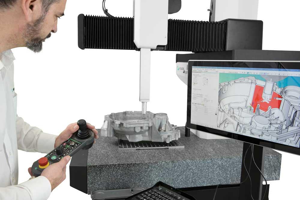
A highlight on a dimensional drawing shows a critical area for measurement on the part on a TIGO SF CMM. Photo courtesy of Hexagon Manufacturing Intelligence.
In an environment where part features are expected to be accurate within microns—and proven so—coordinate measuring machines (CMMs) are becoming industry’s workhorses. Precise measurement, however, takes time, and parts can line up. Parts waiting in a CMM queue can delay production or, perhaps worse, bad parts can continue in-process because critical changes based on measurement data haven’t been communicated. Measurement bottlenecks need to go.
The speed of the measurement itself is somewhat constrained by how fast the CMM can move and the type of sensing being used, but overall process time can be reduced by using metrology software that trims the time spent creating measurement routines, executing those routines, and communicating results. Viewing the measurement function as central to the manufacturing process rather than a final step in component creation can also positively affect overall measurement time and translate to faster production.
Ken Woodbine, product line manager of metrology software at Hexagon Manufacturing Intelligence, said, “When you are developing measurement requirements, typically the master CAD models are available for creating the measurement routine. Having CAD data is a prerequisite to maximizing the speed of measurement work flow.
“Creation of a measurement object can be divided into two areas: the nominal definition and the measurement strategy. The nominal definition comes directly from the CAD and includes what type of feature is to be measured—a cylinder, a plane, a cone, etc. A single click into the CAD object can define the nominal information.
“The measurement intent is typically a communication through a blueprint or drawing that contains the geometric tolerancing that reflects the measurement intent. For example, you can tell the program to probe 10 hits on a feature or scan a component in a spiral pattern. You teach it some guidelines and rules. For example, you can tell it to use one strategy when measuring a high-tolerance feature and a different strategy if it’s a large feature.
This ‘expert system’ approach further reduces the time and uncertainty involved in the measurement creation task.”
Add PMI to CAD Models
Incorporating the product manufacturing information (PMI), or geometric dimensions and tolerancing (GDT), as part of the master model can eliminate the need to spend time creating a separate measurement drawing. The GDT is then loaded along with the CAD model. Using this information simplifies the easy selection of features to be measured, as well as the selection of measurement strategies, reducing the amount of time the component spends on the CMM table.
Scott Lowen, software product manager at Zeiss Industrial Metrology, said, “Adding PMI to CAD models is the biggest contributor to speeding up measurement planning. It may be more work upfront in product design and modelling, but it provides big advantages downstream. It reduces the number of steps taken to build the measurement plan and can save up to 80 per cent of the time involved with measurement planning.
“Not only does it save time in creating the measurement plan, it provides a more consistent and accurate measurement plan between different operators. With PMI the steps taken to build measurement plans are simplified and reduced.”
Lowen continued, “More time is invested in modifying, optimizing, or editing these programs to accommodate engineering changes. Or only a small set of a part’s dimensions need to be inspected. Linear CMM programs have a dependent alignment that can prevent a programmer from running part of a program or making required changes, so often a new program is crated from scratch. Using a software that builds a plan by working objects that represent each drawing dimension as a measurement task eliminates the need to write a new program if the entire part does not need to be measured. When CMM users have the flexibility to run and measure only the critical dimensions, they will reduce the work load on the CMM, keeping it free for other work or to measure other parts.”
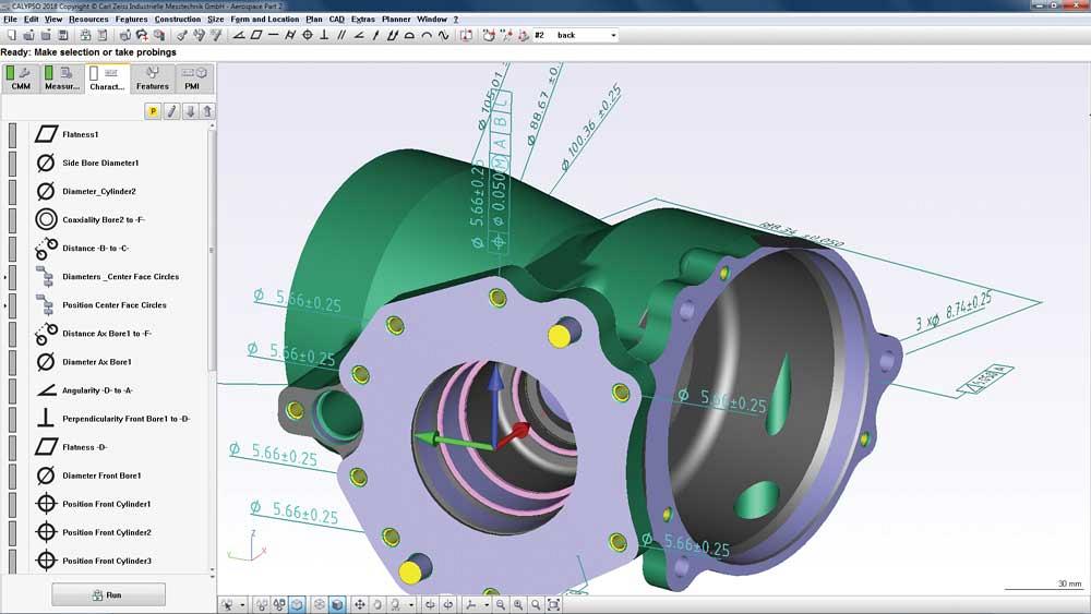
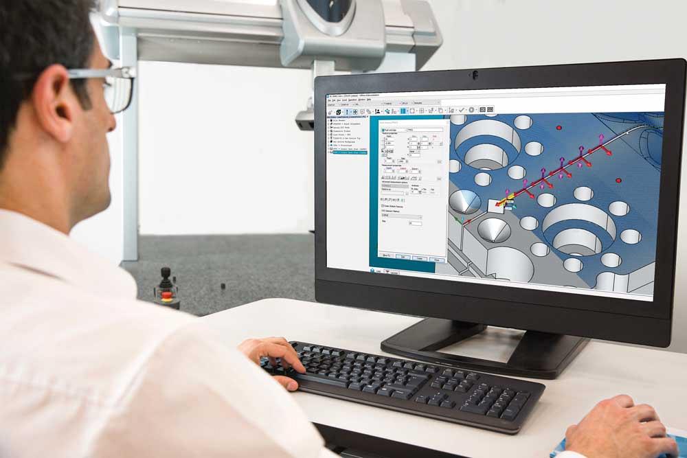
Programming can be as simple as double-clicking PMI from the CAD model, shown in CALYPSO software, and the optimized measurement strategy and probe path are applied. Photo courtesy of Zeiss Industrial Metrology.
Generating the CMM program in advance of production also can help speed parts through the measurement verification.Peter Detmers, president of Mitutoyo Canada, said, “Using 3-D CAD data to develop a CMM program in a virtual environment allows manufacturers to use CAD-based models in advance of a product being manufactured. Then the program is ready when the part is completed by manufacturing.”
Rely on Software
More automation within the software is making the programming task easier by reducing the number of decisions that the programmer needs to make. For example, some software programs can optimize the probing path and choose the best probe to measure a feature.
“It’s not just about selecting the least amount of travel but also selecting the proper probe size. If the change rack has five different styli tips that are all usable, the software will pick the one that is best-suited for measuring the feature—the smallest or largest diameter that will work, or the longest working length—whatever will be most appropriate,” Detmers said.
“The software can test the validity of the GDT. We still see control frames that have illegal or incorrect measurement callouts—where measurement is not possible the way the model or features have been created. The software can go through and highlight any lines where there are errors so they can be corrected in advance of measurement or manufacturing.”
From the hardware perspective, fixturing to secure parts that can’t withstand the probing without shifting can be made easier and faster through CMM software options. Detmers said, “Often parts that are put on a CMM for inspection are too light for the probing force so they have to be clamped down or rigidly held in a fixture. Some software programs can save setup time by choosing what components are needed to build the fixture to secure the part.
“If the next part to be measured is a different shape or size, a fixture built on a common base plate can be broken down and reconfigured or another base plate with the new fixture prepared in advance can provide a new setup.”
Put Measurement at the Center of Production
Traditionally thought of as a final check at the end of production, measurement is moving to the center of the manufacturing process with software’s connectivity options. “When I create a measurement routine, I normally don’t know anything about the machine tool that was or will be used, and many manufacturers don’t think about using that information to optimize measurement strategies,” Woodbine said.
“We are looking at how we can streamline the manufacturing process starting with CAD and creating the CAM programs that are going to be tailored to a particular kind of machine. Then manufacturers can use the information embodied in the cutting process to aid measurement and other farther upstream processes. For example, certain parameters, like feed and speed, are required to communicate with the CAM program, which drives a tool to cut metal while getting the optimal surface to adhere to the required tolerances. The same information that informs how to cut the component can also inform how to measure it,” Woodbine continued.
“For example, if a cylinder is drilled versus milled, it is going to have a different finish and probably different tolerances, so a different measurement strategy will be applied. Using this kind of information the software can tell if the component has a reamed high-finish surface, for example, so fewer hits can get the required measurement result and the measurement process can be completed faster. If the hole is drilled, more hits may be required or perhaps a scan.”
Measuring data can be used to drive changes to the production process. Detmers said, “You can use measuring data to make production changes as quickly as possible. It goes back to the statistical data that can be derived from a population of measurements on a part or process to determine whether the process is stable, in control, out of control, or trending. Whether it’s a CMM on the floor or a series of height gauges, micrometers, or calipers, the data can be collected to the same database, giving the operator the opportunity to react and prevent something that is trending from becoming problematic.
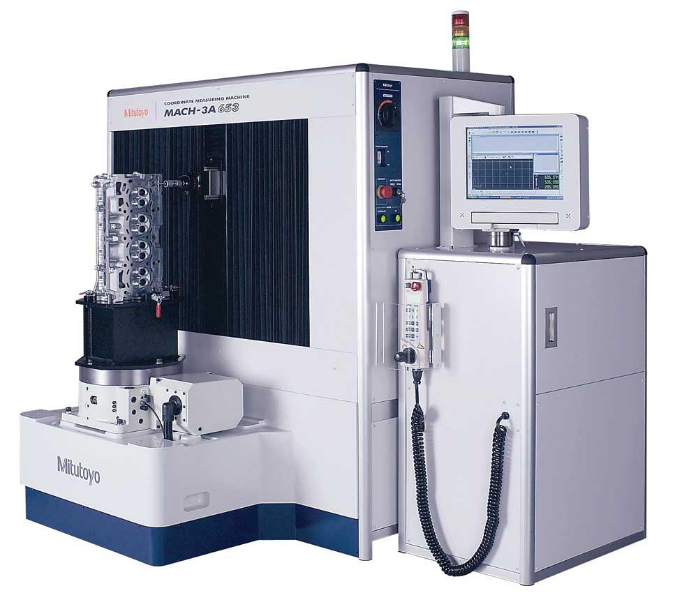
Mitutoyo’s MiCAT Planner software automatically generates full CMM programs by opening the 3-D annotated model. Photo courtesy of Mitutoyo Canada Inc.
“If you take this type of data use one step further, there are software products on the market that allow updating or changing the machine tool programs based on the measuring data. It can avoid rework down the road.”
Automatic, cloud-based notifications are built into some programs. Woodbine said, “Think about an engineer who is waiting for results or an operator who is responsible for being sure the CMM isn’t idle. They could both be working on other tasks and know that they will receive the data they need as soon as it is available.”
Use One Software Package
Building more flexibility into CMM software programs is a definite trend. Metrology software that can be used on multiple machines is replacing proprietary software for each CMM brand. This saves having to train operators on numerous software programs and allows programs to be transferred from one CMM to another without a complete rewrite.
Lowen said, “Most CMM software packages have direct interfaces so they can be installed, relatively inexpensively, on another OEM’s machine. This provides the capability to move one measurement plan to another machine without translation. The translation, like with human languages, may not be 100 per cent, so there may be a component of editing, but the work load is greatly reduced, and operators only need to be trained and familiar with one software.”
“CMMs are great on their own,” said Woodbine. “They are profitable and effective and manufacturers appreciate them. Now, creating connection points where none existed, providing feedback loops to machine tools, and providing data analysis that used to take hours in minutes is a major initiative for manufacturing intelligence.”
Associate Editor Sue Roberts can be reached at sroberts@canadianmetalworking.com.
Hexagon Manufacturing Intelligence, www.hexagonmi.com
Mitutoyo Canada Inc., www.mitutoyo.ca
Zeiss Industrial Metrology, www.zeiss.com/metrology

subscribe now


Keep up to date with the latest news, events, and technology for all things metal from our pair of monthly magazines written specifically for Canadian manufacturers!
Start Your Free Subscription- Stay connected from anywhere

Easily access valuable industry resources now with full access to the digital edition of Canadian Metalworking.

Easily access valuable industry resources now with full access to the digital edition of Canadian Fabricating & Welding.
- Trending Articles
1
Automating additive manufacturing

2
Sustainability Analyzer Tool helps users measure and reduce carbon footprint

3
CTMA launches another round of Career-Ready program

4
Sandvik Coromant hosts workforce development event empowering young women in manufacturing

5
GF Machining Solutions names managing director and head of market region North and Central Americas